Biosensor Array Galvanic Skin Response
This page is part of the Biosensor Array Project
Team Members
Primarily researched and prototyped by Drew Fustini after handover from Phil Strong. Please check with Drew for any clarification.
Current GSR sensor prototype
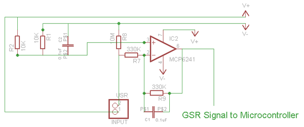
The prototype is based heavily on the Truth Meter circuit from: http://produceconsumerobot.com/truth/
Sean Montgomery, owner of the above site, built a GSR circuit that uses no micrcontroller and a low & high pass filter in the circuit to create a 0.48Hz to 4.8Hz band pass.
Schematic: http://produceconsumerobot.com/truth/content/GSR_schematic_04.png
This circuit was created by Sean for an earlier version of his Truth Wristband project. This circuit, referred to as the Truth Meter, is used at as the biosensor array GSR prototype as it produces a simple analog output that is already filtered. This reduces the complexity of the Arduino code and the graphing display application on the computer.
The Truth Meter circuit is featured in Make Magazine Vol 26 (Spring 2011) in the biosensor article written by Sean.
- Make Magazine: The Truth Meter
- MakerShed Truth Meter kit:
- Truth Meter kit assembly & usage video by Make:
Truth Wristband
The GGHC biosensor GSR sensor is based on a earlier version of Sean's work. His latest GSR is the Truth Wristband v5. This circuit has just a low pass filter with the high pass filter done in software on the PIC.
- Truth Wristband kit video
- Truth Wristband kit Maker Shed:
Schematic:
http://www.produceconsumerobot.com/truth/content/Truth_Circuit.png
Finger contacts
One key part of GSR is how the two probes will attach to the body to measure skin resistance. All GSR projects I found use the fingers, either one or two.
Options:
- Thumbtack
- The first circuit I built was the 'Evil Genius...Arduino' book Lie Detector circuit which used thumbtacks in a breadboard. I also used this when I built the Chris3000 GSR circuit but didn't get very good results.
- Nuts
- Cornell EDA and Chris3000 GSR use nuts soldered onto the ends of wires. I never tried this.
- One Finger Strap
- I ordered the Truth Wristband kit which came with finger strap which I built. It goes onto one finger and has two silver tabs in it which as the two GSR probes.
- Two Finger Straps
- I built these according to the Truth Meter instructions. Velcro tape has copper foil attached with a wire soldered onto it.
Issues:
- Neither thumbtack or nut is ideal as one needs to press against or hold onto. Ideally for the biosensor array, one needs to be able to move freely within the classroom
- Both one and two finger straps generate a good signal if hand is held still. However, movement of the finger like bending causes the contact between the skin and cuff to change which alters the resistance. This registers as a false positive GSR event.
- I contacted Sean Montgomery regarding this problem who gave this advice on spurious input:
"The problem you're experiencing is that when you move, you change the amount
of contact between your finger and the electrode, thereby changing the
resistance of the junction... exactly what the GSR is measuring. You can try
to find a part of the body that is less likely to move during your
behaviours of interest. I've gotten decent GSR from the wrist and not much
success from the forehead, but fingers are the best I've found. You
can measure GSR from numerous locations and reject spurious changes that
only occur on one or two of the locations. You can also try to characterize
the waveshape of real GSR responses and reject resistance changes that don't
fit that criteria."
Measuring Actual Skin Conductance
Some projects like the Cornell EDA project used a Wheatstone bridge and op-amp (configured as difference amp). With this circuit and microcontroller software, they were able to calculate the exact resistance of the skin and thus the skin conductance:
http://courses.cit.cornell.edu/ee476/FinalProjects/s2006/hmm32_pjw32/hardware.png
This would have been a good measurement for the biosensor array but Drew was not able to get their circuit to work correctly. Drew tried both with LM324 quad opamp using 2x voltage follower (to buffer) and 1x as the difference amplifier but saw no signal on the scope. Drew also tried using dual Micrcochip Op-Amp MCP6002 as voltage follower to buffer each input going into the TI INA114 instrumentation amp.
However, no appropriate GSR signal was seen on scope unlike the above Truth wristband circuits by Sean Montgomery. Further development may likely would have resulted in working Wheatstone bridge-based circuit however, time did not allow given and working circuit of a different type was already acheived.
The Cornell EDA project was based on this GSR sensor for MRI machine monitoring by Minn State Univ. This project used a Wheatstone bridge and an instrumentation amp IC. The link on the Cornell EDA page is broken but it is still available via the wayback machine at:
http://web.archive.org/*/http://physweb.mnstate.edu/shastri/EDABoxPaper.ppt
Note: the circuit using a wheatstone bridge and amplifier is also referred to as a bridge transducer amplifier like in the TI INA114 datasheet on page 12: http://focus.ti.com/lit/ds/symlink/ina114.pdf
Related Links
- Arduino GSR project with Processing (with Op Amps): http://www.chris3000.com/archive/galvanic-skin-response/
- Arduino GSR project with Processing UI (no ICs): http://cwwang.com/2008/04/13/gsr-reader/
- Cornell project, EDA Sensor: http://instruct1.cit.cornell.edu/courses/ee476/FinalProjects/s2006/hmm32_pjw32/index.html
- Massimo of Arduino: Heart Rate & GSR shield built on protoshield: http://www.flickr.com/photos/mbanzi/172472639/
- LED output: http://www.youtube.com/watch?v=lPWaGYKQ5ew
- Attached via fingers and wristband: http://www.mustafab.com/blog/?p=437