Talk:ShapeOko2 CNC Router
10.19.2016 - Danny Blanchard: Installed .22uf capacitors on gShield limit switch pins 9,10, and 12: all 3 terminated to pin 14 (Ground). Ran a program with hard limits active, and there were no spurious hard limit trips like before. I also made some temporary foam endstop limits for the positive X and Y directions, but they'll need to be replaced with something better in the future. Soft limits were also set at X255mm and Y285mm, which are just a millimeter before the hard limits would be activated. I installed new spindle mounts that I printed at home, then trammed the spindle off a hex-bar of steel and a 123 block I found in the cold metals area. I also squared the X and Y rails using the steel hex bar and a sheet of "feeler paper." The waste board is bowed in the middle (along the x-axis) and could use some 20x20mm supports under it to prevent this bowing. I moved the e-stop to a better location per membership discussion and secured it temporarily to the frame. The spindle control knob was installed into the temporary backboard (just so it wasn't dangling: I'm not committed to it's present location long-term), then I used my digital tachometer to make a basic speedometer. Lastly, I 3D printed two work-locating fences that match the stud spacing on the waste board, so feel free to play with those if you so choose.
10.14.2016 - Danny Blanchard: Cut and installed a temporary MDF board across the back of the machine to mount the power supplies, control board, PWM spindle speed controller, all with the aim to make moving the machine around easier (it will be getting a new home soon, and these loosely-attached components would likely have sustained some damage). It was pointed out that with this backboard in place the ability to feed a large piece of material through the machine has been lost (a great observation that I hadn't considered: this will be changed). Also, the E-stop switch was temporarily moved to inside the frame to aid in moving the machine, but also to give it a non-dangling-by-the-wires mounting location. I agree that it is not in an ideal location, but I believe that we can find a better, more-permanent solution when this machine gets moved to it's new location (or feel free to modify it now! : ). The current location is not in danger of being crashed into by the spindle, as it is outside of the physical limits of where the gantry and spindle can reach. I also discovered that some of the stepper motor wiring on one of the Y-axis motors was faulty and causing missed steps, and this may have been a contributing factor to the over-heating described by some members during the summer. I also milled-down a portion of the wasteboard that was pulled up around one of the metal hold-down insert nuts. GRBL 0.9j has been re-loaded onto the Control board after some mis-communication on my part with another user, and the homing function has been enabled but the buggy EMI-susceptible hard limits are disabled until I can get some .47uf capacitors installed to absorb the noise. After reading some input from other members, I think this machine is nearly ready to be put back into full operational status. But before we do that, there are two things I'd love to see happen: 1. Get the hard limits working (I know they're not needed for every user, but they'll help in keeping the machine from getting out-of spec as quickly due to accidental crashes), and 2. Confirm that the machine is set up to work with a few different tool-chains without having to adjust GRBL settings. Ideally it would be able use Universal G-code Sender or Chilipeppr with whatever CAM program you prefer (Fusion 360, Vetric, others?), but also use Inventables CAD/CAM/Sender Easel. IMO, only having one system or the other would be a bummer. As a last note, I'd like to thank everyone who has voiced their opinions on the changes to this machine: it has all been professional, helpful, and friendly: let's keep up the good work! Thanks!
10.6.2016 - Danny Blanchard: Downloaded and compiled GRBL v0.9j onto the gShield/Uno. Homing and hard limits now work (Pin 12 is now used for the Z-axis limit switch, as opposed to Pin 11 in v0.8c), although I'm still getting the occasional mid-project "Alarm: Hard Limit" that is likely due to excessive RF noise (I'll be attacking this next) from the spindle and other electronics. The machine (by design) will not move until a homing cycle has been run (send "$H" via Universal G-Code Sender command line console). Home position (X0 Y0 Z0) is located on the left side of the machine as you look at it, closest to the operator, and Z homes all the way to the up top. After doing some settings debugging (acceleration, arc, limit direction inversions, feed/seek/homing rate adjustments) I was able to make some basic, yet exciting cuts. First I generated a usable G-code using Fusion 360 and their "Generic GRBL" post-processor setting. After some tweaking on the side of GRBL, I was able to get 2D and 3D Adaptive clearing (HSM stuff) working, as well as helical ramping/boring.
9.12.2016 - Danny Blanchard: Normally Open (NO) Homing switches installed on X, Y, and Z-axis. Positive Z-axis stop plate installed to prevent top of spindle from crashing at the top of it's travel. Each axis has been wired with a 330ohm resistor connected to 5vdc, as seen below (colors in graphic are wrong: X is actually yellow wire, Y blue wire, Z is orange wire, and ground is black wire). V-wheels and rails all cleaned with a toothbrush: lots of gunk (smooshed wood dust, I believe) on the anodized rails. Also replaced some twist-nuts with solder/heatshrink connections, but there is still more to do in that regard. The motion control board (GRBLShield, pronounced "girr-ble, gerbil, or garble": whichever you prefer) is currently running GRBL v0.8C, and I'm having some difficulty getting the homing direction invert setting ($18) to produce any change. Currently the axis move in the positive direction (away from a lower LH zero home) when the $H command is sent, but changing the $18 value from 0 to 1 makes no change. I'm considering compiling the newest version of GRBL, v0.9J, as the versions since 0.8c have addressed various homing bugs which I believe we're currently experiencing. So next step is to compile and flash using the Arduino IDE, and go from there. https://lh4.googleusercontent.com/-FhXABwKcb-I/UvMhBLTESlI/AAAAAAAADCI/kfE-f7jkrwc/s800/cnc_limit_switch_c3.png
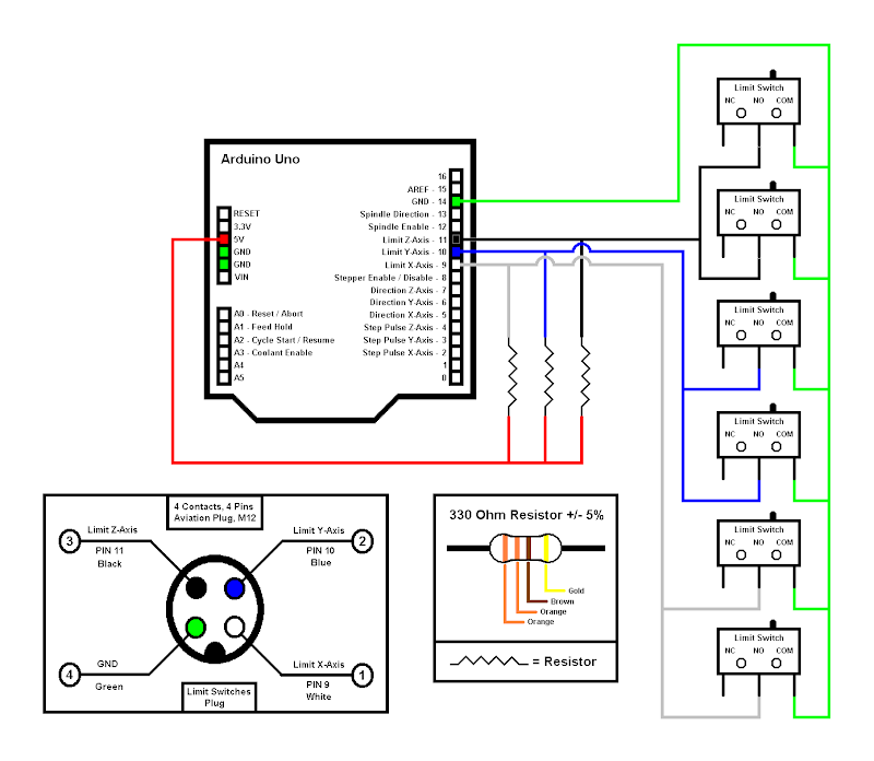
9.8.2016 - Danny Blanchard: Drag chain bracket installed, new lock washers installed (machine can now travel freely until it crashes... :). GRBL shield and Arduino Uno were removed and bent/disconnected pins repaired (likely due to rough handling?). E-stop switch backing nut tightened. Machine ran fine on Easel and with GRBL Controller, but it still needs work (below).
9.7.2016 - Danny Blanchard: Machine cleaned, belts tensioned, power supplies temporarily mounted to wall, wires organized and secured with zip ties. Spindle control and E-Stops tested, both working.